


Co-Extrusion Mould for Door & Window Profiles | Guide
2026-07-25 22:31Co-Extrusion Moulds for Door and Window Profiles: How Chinese Tooling Engineers Deliver Premium Surface Technology for OEM Brands
A European window brand specifying an anthracite grey exterior with a clean white interior finish. A North American OEM client requiring woodgrain-effect door frames that maintain colour stability for 25 years under UV exposure. A premium residential developer in Singapore demanding PMMA-capped profiles that match RAL colour standards across an entire building facade.
All three specifications share a common production requirement: a co-extrusion mould for door and window profiles that can bond two chemically distinct polymer streams — at different temperatures, different viscosities, and different flow rates — into a single dimensionally accurate profile with an interface so stable that delamination is not a field failure mode but a theoretical concern.
For premium window brand manufacturers, product R&D managers, and OEM procurement teams, the hesitation about Chinese tooling for co-extrusion applications is understandable. Co-extrusion die engineering is genuinely more demanding than single-material extrusion. The question is not whether complexity exists — it does — but whether qualified Chinese manufacturers have the engineering depth to handle it at the level that premium window brands require. This guide answers that question with engineering specifics, process transparency, and the technical criteria that distinguish capable co-extrusion tooling partners from those who are not.
What Co-Extrusion Actually Is — and Why It Is Engineering-Intensive
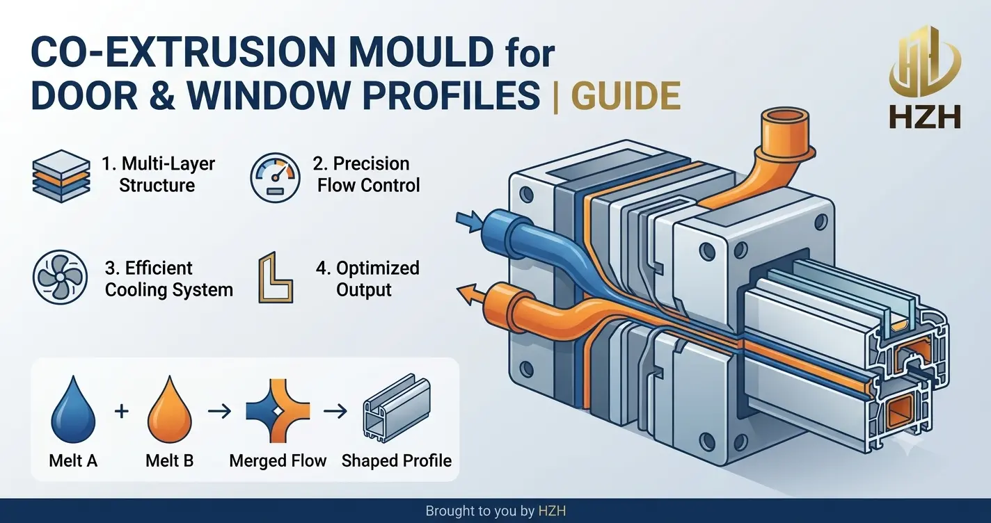
Co-extrusion is a simultaneous multi-material extrusion process in which two or more distinct polymer melt streams are combined within a single die head, emerging as a unified, bonded profile cross-section. For door and window profile applications, co-extrusion serves two primary functions: surface performance enhancement and aesthetic differentiation.
The Two Core Co-Extrusion Architectures
Architecture 1: Substrate-Cap Co-Extrusion (Performance Layer)
A structural substrate material — typically rigid uPVC or WPC — is simultaneously extruded with a thin surface cap layer of a higher-performance polymer. The cap layer, ranging from 0.3–1.5 mm depending on application, provides properties the substrate cannot deliver: UV stability for ASA caps, optical clarity and scratch resistance for PMMA caps, or enhanced weathering performance for modified acrylic formulations. The substrate provides structural rigidity and dimensional stability at lower material cost.
Architecture 2: Dual-Colour Co-Extrusion (Aesthetic Differentiation)
Two streams of the same base polymer — rigid uPVC — are simultaneously extruded in different colours to produce profiles with distinct interior and exterior colour faces. The interior face (white or cream in European residential applications) and the exterior face (RAL 7016 anthracite, RAL 8017 chocolate brown, or custom colours for OEM specifications) are divided by the thermal break zone or profile geometry, with a carefully engineered melt interface between the two colour streams.
Why Co-Extrusion Die Design Is Fundamentally More Complex
A single-material profile die manages one melt stream with one temperature, one viscosity, and one flow behaviour. A co-extrusion die manages two or more melt streams simultaneously — each with different processing windows, different pressure characteristics, and different responses to the die geometry they share. The engineering challenge is making these streams arrive at the interface zone at compatible conditions: matched flow velocity, compatible melt temperatures, and interface pressure sufficient to create molecular-level bonding without distorting either stream's dimensional contribution to the final profile.
Three specific failure modes that only occur in co-extrusion dies — and that only an experienced co-extrusion mould engineer can prevent through design:
Interface instability — viscosity mismatch between the two melt streams at the interface zone creates wave-pattern distortion of the bonding surface, visible as a sinuous line at the colour boundary in dual-colour profiles
Cap layer thickness variation — unequal flow distribution in the cap layer manifold produces profiles where the ASA or PMMA layer is 1.2 mm at one profile section and 0.4 mm at another — compromising UV protection uniformity and creating visual surface variation
Delamination under thermal cycling — inadequate interface bonding pressure or incompatible polymer pairing produces cap layers that appear bonded at extrusion but separate progressively under the thermal cycling of installed window service — a warranty catastrophe for any premium window brand
The Engineering Architecture of a Professional Co-Extrusion Die System
Understanding how a correctly engineered dual colour window profile extrusion die system is structured explains both why it is more demanding to manufacture and what technical markers distinguish a capable supplier from an overconfident one.
The Dual-Manifold Die Head
A co-extrusion die system begins with the die head — the component that receives two separate melt streams from two extruders and manages their routing to the interface zone. The critical engineering element is the dual-manifold geometry: two independent flow channels, each shaped to distribute their respective melt stream evenly across the full width of their designated die section, before the streams meet at the co-extrusion interface plane.
Each manifold must be designed independently using flow simulation — because the two polymer streams typically have different viscosities and require different manifold geometries to achieve the equal distribution that produces uniform layer thickness. A supplier who designs both manifolds identically — treating them as mirror images rather than independent engineering problems — will produce uneven cap layer distribution that no downstream calibration adjustment can correct.
Interface Zone Geometry and Bonding Mechanics
The interface zone — where the two melt streams first contact each other inside the die — is the most engineering-critical feature of any co-extrusion mould for door window profiles. Interface pressure at this zone must be high enough to create intimate molecular contact between the two polymer surfaces — the prerequisite for chemical bonding — while remaining below the pressure level that causes one stream to penetrate and distort the other.
For ASA-over-uPVC co-extrusion — the most common premium window profile architecture — the interface zone is engineered at a location in the die where both streams are at their closest compatible processing temperatures: typically 175–190°C for the uPVC substrate stream and 200–215°C for the ASA cap stream. This temperature differential of 15–35°C is managed through selective die body heating zones — a requirement that adds significant thermal management complexity to the die design that single-material dies do not face.
The Co-Extrusion Calibrator: Where Final Dimensions Are Set
Downstream of the die, the co-extrusion calibrator mould receives the still-hot co-extruded profile and fixes its final dimensions under vacuum cooling. For co-extruded profiles, the calibrator design is more demanding than for single-material profiles because the two bonded materials cool at different rates — a consequence of their different specific heat capacities and thermal conductivities.
If the calibrator geometry does not account for this differential cooling rate, the profile exits the calibration zone with internal thermal stresses that cause warping after the profile reaches ambient temperature — often 2–4 hours after production, creating a warranty problem that is invisible during on-line quality inspection. Professional co-extrusion calibrator design incorporates differential cooling zone management — with cooling intensity graduated across the profile cross-section to achieve uniform temperature distribution at calibrator exit regardless of cap layer and substrate thickness variation.
Material Compatibility Engineering: The Prerequisite That Is Often Skipped
Co-extrusion die geometry is only one half of the engineering challenge. The other half is polymer compatibility — ensuring that the two melt streams are chemically and rheologically suited to bonding with each other under the processing conditions the die creates.
Chemical Compatibility at the Interface
For substrate-cap co-extrusion, the cap polymer must form adhesive bonds with the substrate at the interface zone. For ASA-over-uPVC, this bonding is achievable without adhesive tie layers because ASA contains styrenic components that are compatible with uPVC at the molecular level — provided that interface temperature and pressure are within the bonding window. For PMMA-over-uPVC, compatibility is lower and typically requires a co-extruded adhesive tie layer between the two primary streams — a third melt stream that adds another level of die engineering complexity.
For dual colour window profile extrusion die applications using two uPVC streams, chemical compatibility is inherently high — the two streams are the same base polymer. The engineering challenge shifts from chemical bonding to colour boundary sharpness: ensuring the interface between the interior white stream and the exterior anthracite stream is geometrically precise and dimensionally stable, without the colour diffusion or bleed that occurs if interface pressure is insufficient or melt temperatures are too high.
Rheological Matching: The Viscosity Challenge
Viscosity mismatch between the two melt streams is the most common cause of interface instability in co-extrusion profiles. If the cap stream is significantly less viscous than the substrate stream at the interface zone — as can occur with certain PMMA grades relative to rigid uPVC — the low-viscosity material tends to encapsulate the high-viscosity stream, disrupting the intended geometry of the interface plane.
Managing this requires either compound formulation adjustment — selecting grades with viscosities matched at the processing temperature — or die geometry compensation through specific flow restriction elements that equalise effective viscosity behaviour at the interface. In our engineering team's experience at Huazhiheng Mold, the most reliable approach is to specify the exact polymer grades and grades' melt flow index values before die design begins — and to incorporate this data into the flow simulation that precedes any steel cutting decision.
| Co-Extrusion Type | Cap Material | Key Technical Challenge | Tie Layer Required |
|---|---|---|---|
| ASA over uPVC | ASA (Acrylonitrile Styrene Acrylate) | Temperature differential management | No — inherent compatibility |
| PMMA over uPVC | PMMA (Polymethyl Methacrylate) | Viscosity mismatch + adhesion | Yes — typically required |
| Dual-colour uPVC | Coloured uPVC (same base) | Colour boundary sharpness | No — same polymer family |
| WPC with ASA cap | ASA or PVC cap over WPC core | Differential shrinkage + adhesion | Application-dependent |
| TPE soft-touch co-ex | TPE (Thermoplastic Elastomer) | Shore hardness gradient management | Sometimes — grade dependent |
What OEM-Grade Co-Extrusion Tooling Capability Actually Looks Like
Premium window brands and OEM procurement teams evaluating Chinese co-extrusion mould suppliers need specific technical evidence — not marketing claims — to make a justified sourcing decision. These five capability markers distinguish manufacturers with genuine co-extrusion engineering depth from those offering it as an upsell without the technical foundation.
1. Co-Extrusion-Specific Flow Simulation
Flow simulation for co-extrusion is not the same as single-material simulation with two material entries. It requires software capable of modelling multi-fluid interface dynamics — tracking the boundary between two polymer streams through the full die geometry, predicting interface stability, and identifying encapsulation risk zones before any steel is committed. Ask any prospective supplier to show you a simulation result that includes interface position and stability analysis — not just pressure and temperature distribution maps for a single melt stream.
2. Documented Co-Extrusion Project History
Request non-confidential case examples of co-extrusion die projects for window or door profiles. Specific evidence should include: the co-extrusion architecture (ASA-cap, dual-colour, PMMA-cap, or other); the profile application (window frame, door panel, sash, glazing bead); the polymer combination and grades specified; and the production validation outcome — cap layer thickness uniformity measurements, interface stability confirmation, and delamination test results. A supplier with no documentable co-extrusion project history is not a co-extrusion specialist — regardless of what their capability brochure states.
3. Dual-Extruder Line Compatibility Engineering
Co-extrusion die systems require two extruders — typically a primary twin-screw extruder for the substrate and a secondary single-screw extruder for the cap layer — whose output must be precisely coordinated in terms of flow rate and pressure. The die must be engineered with the buyer's specific secondary extruder model in mind, because the cap layer manifold geometry is calibrated to that extruder's output pressure characteristics. Confirm that the supplier requests and uses secondary extruder specifications — not just primary extruder data — in their die design process.
4. Calibrator Design as Part of the Die System
As discussed above, the calibrator is not a separate procurement for co-extrusion applications. A supplier who designs the die head without co-designing the calibration tooling — leaving calibrator procurement to the buyer as an afterthought — is not offering a co-extrusion system. They are offering a co-extrusion die that may or may not work with whatever calibrator the buyer subsequently sources. For OEM applications where dimensional consistency across production batches is a brand quality requirement, this approach is not acceptable.
5. Colour Matching and RAL Standard Compliance
For dual-colour and ASA-capped OEM profiles, colour accuracy is a brand specification requirement. The co-extrusion die must produce cap layer surfaces with sufficient uniformity — in both thickness and temperature history — that the colour value of the extruded surface matches the specified RAL standard within the tolerance that colour measurement instruments can detect. This requires cap layer thickness uniformity of ±0.05 mm across the full die width and die body thermal management precise enough to prevent colour shift from localised temperature variation in the cap stream.
Developing a dual-colour or ASA-capped co-extrusion profile for your window system?
Huazhiheng Mold provides complete co-extrusion die system engineering — dual-manifold die head design, multi-fluid flow simulation, matched calibrator tooling, polymer compatibility assessment, and full production debugging — for premium window brands and OEM clients across Europe, North America, and global markets.
Request a Co-Extrusion Technical Assessment →The OEM Project Process: From Colour Specification to Validated Production
For premium window brands and OEM clients commissioning a co-extrusion profile programme, understanding the development process timeline sets realistic expectations and prevents the schedule compression that creates quality compromises.
Phase 1: Material and Design Specification (Days 1–10)
The project begins with a complete specification review: profile cross-section drawing with critical dimensions and tolerances; cap layer thickness specification and uniformity tolerance; polymer grade selections for both substrate and cap streams with melt flow index data; colour specification (RAL number with ΔE tolerance); secondary extruder model and output capacity; and any delamination or weathering test standards the finished profile must meet (EN 513 for colour stability, EN 12608 for uPVC profile classification, or OEM-specific weathering protocols).
At this stage, the engineering team assesses polymer compatibility, identifies whether a tie layer is required, and produces a preliminary die architecture proposal for client review before any simulation work begins.
Phase 2: Flow Simulation and Design Approval (Days 10–18)
With specification confirmed, multi-fluid flow simulation models both melt streams through the proposed die geometry — generating interface stability analysis, cap layer thickness distribution prediction, and pressure balance confirmation across the dual manifold system. The simulation output is shared with the client's R&D team as part of a formal design approval package, alongside the calibrator thermal model showing differential cooling zone distribution.
Design approval sign-off before steel cutting is non-negotiable for OEM-grade co-extrusion projects. Changes identified at simulation stage cost days. Changes identified after machining cost weeks and significant rework expense.
Phase 3: Die Manufacture and System Assembly (Days 18–48)
Manufacturing proceeds through CNC machining of die head components, wire EDM of critical interface zone geometry, vacuum hardening and nitriding surface treatment, precision assembly with dimensional verification at each stage, and calibrator manufacture in parallel with die head completion. H13 tool steel is standard for co-extrusion die heads — the elevated processing temperatures of ASA and PMMA cap streams require the thermal stability that P20 does not provide at co-extrusion temperatures.
Phase 4: Production Trial and Validation (Days 48–58)
The complete die system — die head, co-extrusion adaptor, and calibrator — is trialled on an extrusion line with the buyer's specified polymer grades. Trial output is measured for cap layer thickness uniformity (cross-section sampling at 5 points across profile width), colour value against RAL specification (colorimeter measurement), interface bond integrity (peel test at 180° per relevant test protocol), and dimensional conformance against profile drawing tolerances. A formal validation report documents all trial measurements against specification — the evidence package that OEM procurement teams require for supplier qualification.
Addressing the Capability Scepticism: What the Evidence Shows
The perception that Chinese mould manufacturers cannot deliver OEM-grade co-extrusion tooling reflects a market reality from 10–12 years ago — not 2026. The specific evidence that qualified manufacturers provide to address this scepticism includes:
Jinwei Global Extrusion Engineer Certification — the industry-recognised credential for advanced extrusion engineering competence, including co-extrusion process design. Huazhiheng Mold's engineering team holds this certification, providing independent verification of technical capability beyond ISO documentation
ISO 9001 and IATF 16949 certification — quality management frameworks that require documented process control for every stage of die design and manufacture, providing OEM clients the audit evidence their supplier qualification processes require
Flow simulation capability with multi-fluid interface modelling — the technical infrastructure that distinguishes co-extrusion engineering from co-extrusion machining
Validated OEM export projects — non-confidential evidence of co-extrusion die systems delivered to premium window brands and OEM clients, with documented production validation outcomes
OEM procurement teams who apply the same supplier qualification process they would apply to a European or North American tooling source — requesting certifications, simulation evidence, project history, and validation documentation — find that qualified Chinese co-extrusion die manufacturers meet the same evidence standards. The qualification process, applied rigorously, is the correct filter. Country of origin is not.
Key Takeaways
Co-extrusion die engineering is a distinct technical discipline — dual-manifold flow simulation, interface zone bonding mechanics, differential cooling calibrator design, and polymer compatibility assessment are all prerequisites for OEM-grade co-extrusion tooling that cannot be substituted by general extrusion die manufacturing experience alone
Five specific capability markers — multi-fluid flow simulation, documented co-extrusion project history, secondary extruder compatibility engineering, integrated calibrator design, and RAL colour compliance methodology — provide OEM procurement teams with the verifiable evidence needed to qualify a Chinese co-extrusion mould supplier to premium brand standards
The development process has non-compressible phases — specification review, simulation and design approval, die manufacture, and production trial validation are sequential dependencies where compression at any stage creates quality risk that surfaces as a brand warranty problem, not a tooling problem
As the premium window market's demand for dual-colour, woodgrain-effect, and ASA-capped profiles continues its structural growth through 2026 and beyond — driven by architectural specification requirements and the renovation of Europe's ageing building stock — window brands and OEM clients who establish verified co-extrusion tooling partnerships with technically qualified manufacturers gain both production capability and cost competitiveness that import-dependent or Europe-only tooling strategies cannot match.
Ready to qualify Huazhiheng Mold for your co-extrusion window profile tooling programme?
We provide complete OEM supplier qualification documentation: ISO 9001 & IATF 16949 certificates, Jinwei Extrusion Engineer credentials, multi-fluid simulation capability demonstration, co-extrusion project references, and a technical proposal for your specific profile and polymer combination — within 5 business days of receiving your specification.
Request Your OEM Qualification Package →Frequently Asked Questions
What is a co-extrusion mould for door and window profiles?
A co-extrusion mould for door and window profiles is a die system that simultaneously processes two or more distinct polymer melt streams — from two extruders — combining them into a single bonded profile cross-section. The system comprises a dual-manifold die head that manages independent flow routing for each stream, an interface zone where the streams bond under controlled pressure and temperature, and a matched calibrator with differential cooling zones that accounts for the different thermal properties of each bonded material. The result is a profile with different surface and structural properties that a single polymer cannot achieve alone.
What is the difference between ASA co-extrusion and dual-colour co-extrusion for window profiles?
ASA co-extrusion applies a thin cap layer (0.3–1.5 mm) of Acrylonitrile Styrene Acrylate over a uPVC substrate — primarily for UV resistance and colour stability enhancement. The two materials are chemically different polymers with different processing temperatures. Dual-colour co-extrusion uses two streams of the same base polymer (uPVC) in different colours to produce profiles with distinct interior and exterior colour faces. The engineering challenge for ASA co-extrusion is temperature differential management; for dual-colour, it is colour boundary sharpness and interface pressure control.
How do I verify that a Chinese co-extrusion mould supplier can meet OEM quality standards?
Request five specific evidence items: multi-fluid flow simulation capability with interface stability analysis (not just single-material simulation); documented co-extrusion project examples with cap layer thickness uniformity measurements and delamination test results; confirmation that secondary extruder specifications are used in die design (not just primary extruder data); integrated calibrator design as part of the die system proposal; and RAL colour compliance methodology with colorimeter measurement protocol. Suppliers holding ISO 9001, IATF 16949, and Jinwei Extrusion Engineer certification provide the documented quality framework that OEM supplier qualification processes require.
Why does co-extrusion calibrator design matter for window profile quality?
The calibrator fixes final profile dimensions under vacuum cooling — but co-extruded profiles cool at different rates in different cross-section zones because the cap layer and substrate have different thermal properties. A calibrator not designed for differential cooling produces profiles with internal thermal stresses that cause warping after production, often 2–4 hours after extrusion when the profile reaches ambient temperature. This post-production warping is invisible during on-line quality inspection but produces installation and dimensional conformance problems. Integrated calibrator design that accounts for differential cooling rates prevents this failure mode entirely.
How long does OEM co-extrusion mould development take from specification to validated production?
A complete OEM co-extrusion mould development programme — from full specification confirmation through validated production trial — typically requires 50–65 days. This covers: specification review and polymer compatibility assessment (Days 1–10); multi-fluid flow simulation and design approval (Days 10–18); die head and calibrator manufacture including heat treatment and surface finishing (Days 18–48); and production trial with full validation documentation (Days 48–58). Projects that compress the simulation and design approval phases to meet aggressive timelines consistently produce higher correction round frequency — extending total project duration beyond the timeline that proper process discipline would have required.