


Sliding, Casement & Tilt-Turn Window Profile Mould
2026-05-30 00:14Sliding, Casement, and Tilt-Turn Window Profile Moulds: Why Each System Demands a Different Engineering Approach
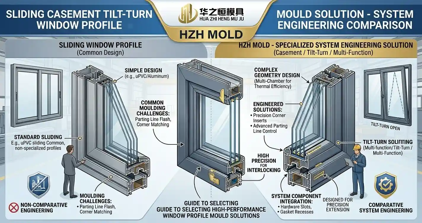
A glazing contractor specifying a 40-storey curtain wall project in Kuala Lumpur and a window fabricator producing sliding patio doors for suburban housing in Dubai face a common engineering problem: their window systems look different, open differently, and seal differently — and every one of those functional differences traces back to the extrusion die that shaped each profile.
For window system integrators, facade engineers, and architectural glazing procurement teams, the critical mistake in mould sourcing is treating profile tooling as interchangeable. A sliding window profile mould solution optimised for a two-track aluminium system cannot simply be adapted for a casement rebate geometry or a tilt-and-turn euro-groove profile — the structural requirements, sealing geometry, and hardware interface tolerances are fundamentally different at the die engineering level.
This guide explains exactly how mould design requirements diverge across the three dominant window system types, what system-level tooling integration means in practice, and how window system developers can source a complete profile mould programme that delivers dimensional fit across every component from day one.
Why Window System Type Determines Mould Architecture — Not the Other Way Around
Window performance — thermal insulation, weather resistance, acoustic attenuation, and operational longevity — is ultimately a function of how well every extruded profile in the system works together. Frame, sash, glazing bead, weather seal carrier, drainage cover, and reinforcement profile must all exit their respective dies at dimensions that achieve designed clearances, compression seals, and hardware engagement across the full operating temperature range.
This systems-level interdependency means that specifying individual profile moulds in isolation — the most common approach among first-time window system developers — produces a fragmented tooling programme where dimensional drift between dies creates assembly problems that no amount of downstream adjustment can fully resolve.
Sliding Window Profile Moulds: The Precision Track Geometry Challenge
Sliding window systems — including two-track, three-track, and lift-and-slide configurations — place unique demands on profile mould design that distinguish them from all other window types. The defining engineering challenge is track and sash interface geometry: the dimensional relationship between the frame track channel and the sash bottom rail must be held within tolerances tight enough to ensure smooth operation across temperature ranges from -15°C to +65°C in markets spanning Northern Europe to the Gulf region.
Track Channel Dimensional Requirements
A sliding window track profile typically incorporates two or three parallel channel sections into which sash bottom rails engage. The width tolerance of each channel must be held to ±0.08–0.12 mm to accommodate the running clearance of the sash pile weatherstrip without creating either excessive lateral play — which causes rattling under wind pressure — or binding that prevents smooth operation at elevated temperatures when aluminium expansion increases sash dimensions.
Achieving this tolerance across a multi-channel track profile — where the die must simultaneously form channels of different widths separated by thin web sections — requires precise die land length differentiation across each channel element. Thicker web sections require longer bearing lengths to slow metal flow; narrower channel webs require shorter lands to maintain equal exit velocity. This flow balancing calculation is what separates a functional sliding window profile mould solution from a die that looks correct on paper but produces dimensional drift within 50 metres of startup.
Sash Bottom Rail and Interlock Profile Co-Engineering
The sash bottom rail profile that runs inside the track channel must be designed and manufactured as a matched pair with the track die — not specified independently. Interlock engagement depth, pile groove width, and running clearance are calculated as a system, with tolerances allocated across both profiles to achieve the designed operating fit.
Casement Window Profile Moulds: Rebate Geometry and Compression Seal Engineering
Casement windows — side-hung, top-hung, and fixed-light configurations — operate on a fundamentally different sealing principle from sliding systems. Where sliding windows rely on pile weatherstrips for a running seal, casement systems use compression seals: the sash closes against the frame, compressing a continuous gasket around the entire sash perimeter to achieve weather tightness.
This sealing mechanism places the most demanding dimensional requirements of any window type on the casement window extrusion die — specifically on the rebate geometry that receives the compression gasket.
Rebate Depth and Gasket Groove Precision
Casement window compression performance depends on achieving consistent gasket compression of 20–35% across the full sash perimeter when the window is closed. Too little compression and the seal leaks under wind-driven rain; too much and operating force exceeds acceptable limits, fatiguing hinges and handles prematurely.
Gasket compression is a direct function of rebate depth consistency. The frame rebate and sash rebate must together produce the designed overlap — typically 8–12 mm for European casement systems — within a tolerance of ±0.10 mm to keep gasket compression within the designed range. A rebate die that produces depth variation beyond this tolerance will create localised leak points that appear only under pressurised water testing — often after the window has been installed in a building facade.
Drainage Channel Integration in Casement Frame Profiles
Casement frame profiles typically incorporate integral drainage channels that direct condensation and wind-driven rain infiltration from the sill area to weep holes at the frame exterior. The geometry of these drainage channels — their width, depth, and baffle positions — must be engineered into the frame extrusion die with sufficient dimensional accuracy to prevent water pooling that causes seal degradation and interior water ingress.
At Huazhiheng Mold, our engineering team's 20+ years of casement die experience consistently shows that drainage channel geometry is the most frequently underspecified element in casement window profile briefs. Buyers focus on visible dimensions — sightline width, rebate depth — and omit drainage specifications entirely, producing dies that meet visual quality standards but fail in weather performance testing.
Tilt-and-Turn Window Profile Moulds: Euro-Groove Hardware Interface Engineering
The tilt-and-turn window — dominant across German, Austrian, and Central European residential construction, and rapidly gaining adoption in commercial projects across the Middle East and Southeast Asia — presents the most complex mould engineering challenge of any standard window type. Its dual-function operation (inward tilting for ventilation, inward turning for full opening) requires sash profiles that simultaneously accommodate:
Euro-groove hardware channel — a precisely dimensioned slot running the full perimeter of the sash that receives the multi-point locking mechanism
Corner joint geometry — sash corner sections must weld cleanly at 45° cuts, requiring specific internal chamber design to prevent voids at weld joints
Dual-seal rebate — tilt-and-turn systems use two compression gaskets (inner and outer) for enhanced thermal and acoustic performance, requiring two separate gasket grooves with independent tolerances
Reinforcement channel compatibility — steel or aluminium reinforcement inserts must engage the sash profile with minimal play to prevent hardware misalignment under operational loading
Euro-Groove Dimensional Criticality
The euro-groove — standardised at 13 mm × 20 mm internal dimensions across the major European hardware systems (Roto, Siegenia, GU, Maco) — must be held to a width tolerance of ±0.05 mm in the tilt-and-turn window profile mould. Hardware engagement pins that drive within this groove require this precision to function across the full operating temperature range without binding or excessive play.
A mould producing euro-groove width variation beyond this tolerance will cause hardware engagement problems that only manifest after installation — typically reported as difficulty locking or unlocking the window, particularly in summer when thermal expansion reduces groove clearance to its minimum.
Corner Weld Chamber Design for Tilt-Turn Sash Profiles
Tilt-and-turn sash profiles are mitre-cut and welded at corners to form the complete sash frame. The quality of these weld joints — their strength, surface appearance, and dimensional accuracy — depends significantly on the internal chamber geometry of the sash extrusion.
Weld chamber walls that are too thin produce visually acceptable but structurally weak corner joints. Internal void positions that create uneven weld contact surfaces produce visible sink marks that require post-weld finishing. Engineering the sash profile die with weld joint performance in mind — rather than optimising purely for extrusion efficiency — is a specialisation that distinguishes experienced window system profile tooling manufacturers from general-purpose die shops.
| Window System | Critical Die Feature | Key Tolerance | Primary Failure Mode if Wrong |
|---|---|---|---|
| Sliding (2/3-track) | Track channel width + sash interlock | ±0.08–0.12 mm | Binding or rattle under temperature change |
| Casement (compression seal) | Rebate depth + gasket groove geometry | ±0.10 mm | Compression seal failure, water ingress |
| Tilt-and-Turn (euro-groove) | Euro-groove width + corner chamber design | ±0.05 mm | Hardware binding, weak corner welds |
| Fixed Light (glazing bead) | Glazing bead snap-fit geometry | ±0.08 mm | Bead rattle, security failure, glass retention |
| Lift-and-Slide (heavy duty) | Roller carriage housing dimensions | ±0.06 mm | Roller misalignment, premature wear |
The System-Level Tooling Approach: Why Integration Beats Individual Die Sourcing
The engineering differences between window types described above converge on a single procurement conclusion: sourcing profile dies for a complete window system from a single, system-aware manufacturer delivers measurably better outcomes than assembling a tooling programme from multiple independent suppliers.
Dimensional Consistency Across the Profile Family
A complete sliding window system may require 8–14 individual extrusion profiles: main frame, track cover, sash bottom rail, sash side rail, sash top rail, glazing bead (two sizes), weather seal carrier, drainage cover, and reinforcement channel. When these profiles are manufactured to a single coordinated tolerance stack — with each die designed in awareness of its interface relationships with adjacent profiles — the assembled window achieves designed clearances and fits without field adjustment.
When the same profiles are sourced from three or four independent die makers, each working to the same nominal drawings but making independent assumptions about fit allowances, the resulting tolerance accumulation frequently prevents the system from assembling correctly without costly profile or hardware modifications.
Coordinated Mould Development Timeline
System integrators and window development engineers working to construction programme deadlines cannot afford sequential mould commissioning — where each die in the family is completed and tested before the next is ordered. A system-level tooling partner can run parallel development across the full profile family, with coordinated design reviews that catch interface incompatibilities before any steel is cut rather than during individual trial runs.
Based on our project experience at Huazhiheng Mold, a coordinated 10-profile window system tooling programme completed in parallel typically delivers the full family to production-ready status in 45–55 days. Sequential individual sourcing of the same 10 profiles consistently takes 90–120 days — with the additional risk of interface incompatibilities discovered only when the full system is assembled for the first time.
Developing a complete sliding, casement, or tilt-and-turn window profile system?
Huazhiheng Mold provides system-level window profile tooling programmes — co-engineering all frame, sash, glazing bead, and accessory dies as a coordinated family with matched tolerance stacking, flow simulation, and parallel delivery scheduling.
Request a System Tooling Consultation →Specifying a Window System Tooling Programme: What Your Mould Partner Needs
To support a complete window system profile tooling programme effectively, a qualified mould manufacturer needs a structured specification package that goes beyond individual profile drawings. Provide the following for each new window system project:
Full profile family drawing set — all cross-sections with interface dimensions and tolerances marked, in DXF or DWG format
System assembly drawing — showing how frame, sash, glazing bead, and accessory profiles interrelate, with designed clearances marked
Hardware specification — brand, model, and critical engagement dimensions for all locks, hinges, handles, and roller systems
Material specification — PVC, UPVC, aluminium alloy grade, or WPC, with formulation data if available
Extrusion equipment list — extruder models and container diameters for each profile type in the family
Performance standard requirements — EN 12208, EN 12210, EN 14351, or equivalent standards the system must achieve
Programme delivery timeline — construction programme dates driving tooling availability requirements
Key Takeaways
Window type drives mould architecture — sliding track clearance, casement compression rebate, and tilt-and-turn euro-groove geometry each require distinct die engineering approaches that cannot be generalised across system types
Interface tolerances are system-level specifications — track-to-sash, rebate-to-gasket, and euro-groove-to-hardware dimensional relationships must be toleranced as a coordinated family, not as independent profile dimensions sourced from separate suppliers
System-level tooling integration compresses programme delivery timelines by 40–50% compared to sequential individual die sourcing — while eliminating the interface incompatibility risk that sequential sourcing consistently introduces at first assembly
In 2026's window market, where facade performance requirements are rising across every major construction segment and project programmes are tightening, window system integrators and developers who invest in system-level profile tooling programmes gain a compounding advantage: faster system launches, higher first-run production yields, and profile families that perform to specification from the first assembled window — not after months of field adjustments.
Ready to commission a complete window system profile mould programme?
Huazhiheng Mold's engineering team co-develops sliding, casement, and tilt-and-turn window profile tooling families as coordinated systems — with matched tolerance stacking, parallel production scheduling, ISO 9001 & IATF 16949 certified quality documentation, and full debugging support across the complete profile family.
Start Your Window System Tooling Programme →Frequently Asked Questions
What is the difference between a sliding window profile mould and a casement window profile mould?
Sliding window profile moulds must produce precision track channels and sash bottom rails engineered as matched pairs, with running clearance tolerances of ±0.08–0.12 mm to ensure smooth operation across temperature extremes. Casement window profile moulds focus on compression rebate depth consistency (±0.10 mm) and integrated drainage channel geometry to achieve weather tightness under EN 12208 water resistance standards. The sealing mechanisms, operational loads, and hardware interfaces are fundamentally different, requiring distinct die engineering approaches for each system type.
Why does a tilt-and-turn window profile require tighter tolerances than sliding or casement systems?
Tilt-and-turn systems use a euro-groove hardware channel that must engage multi-point locking mechanisms across the full operating temperature range. The euro-groove width tolerance of ±0.05 mm is tighter than sliding or casement requirements because hardware pins that drive within this groove have no adjustment capability — dimensional variation directly translates to operational binding or excessive play. Additionally, the dual-seal rebate geometry and corner weld chamber design requirements add further engineering complexity not present in single-function window types.
How many profile dies does a complete window system require?
A complete window system typically requires 8–14 individual extrusion profile dies, covering main frame, sash rails (top, bottom, side), glazing bead in two or more sizes, weather seal carriers, drainage covers, reinforcement channels, and system-specific accessory profiles. The exact count depends on window type complexity — tilt-and-turn systems typically require more profiles than equivalent sliding systems due to their dual-function sash and enhanced sealing requirements.
What is system-level window profile tooling and why does it matter?
System-level window profile tooling means co-engineering all dies in a profile family from a single coordinated specification — with interface dimensions, tolerance stacking, and fit allowances designed across all profiles simultaneously rather than independently. This approach eliminates the dimensional incompatibilities that arise when individual profile dies are sourced from separate manufacturers using independent tolerancing assumptions. System-level tooling delivers correct assembly fit from the first production run, reducing system launch timelines by 40–50% compared to sequential individual die sourcing.
Can the same extrusion mould manufacturer produce both PVC and aluminium window system tooling?
Yes, manufacturers with genuine window system expertise design both PVC/UPVC extrusion dies and aluminium extrusion dies. However, the engineering requirements differ significantly — PVC dies use P20 or H13 steel with nitriding for corrosion resistance, while aluminium dies require H13 with vacuum hardening for high-temperature press conditions. When sourcing a mixed-material window system (aluminium outer frame with PVC thermal break elements, for example), confirm the supplier has documented project experience with both material types before commissioning a combined tooling programme.